

IDEATION
Brainstorming in a sustainable context
The day started great, almost all the group arrived at our headquarters: Anna's apartment. Here we had our mandatory morning ice coffee, and then we were ready for business!
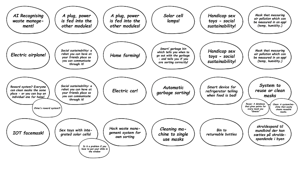
We called the missing members on zoom, and the ideation process started. We started with the KJ technique, silently using our creative minds to push ideas out, as if they were cookies in a bakery. This went on for 5 mins. It was short and productive!
After this we did an interpretation session, where we discussed and clustered the different topics from the brainstorm. The point was to investigate the biggest needs and problems that we were interested in solving. The solution had to fit both our interest and the project defintion.
As all great minds, we thought pretty alike. We all really liked the idea of "Sustainable home farming" and thought it was PERFECT for our project (under the category of: smart buildings/ smart cities).
Our idea was that this product would be a way for us to increase sustainability, and thereby help our precious world :3

IDEAS
April 12, 2025
DETAILING
Abstract concept detailing; creating a plan for the future of our project.
Starting in the second part of the double diamond, we had a good idea of where we wanted the project to go. After our feedback session, we felt pretty confident in our idea, and just needed to refine what had to be done. The idea was a modular smart farm that allows one to effortlessly grow vegetables at home. The "smart" parts of the product would be its automatic watering systems and adjustable lighting system.
PRODUCT REQUIREMENTS DOCUMENT
The first thing on our agenda was to write down our product requirements. The document would highlight the most important requirements. This would give us a better overview of the project as a whole and ensure that the product fit our project description. This also helped us understand which components would be needed for the completion of the project.
After having decided on our requirements, we created a function-means tree to specify the features we wanted to implement. The point of the process was to investigate the specific means necessary for the achievement of the product's functions. This was done iteratively as we had to go back to documents several times to add our newly gained knowledge.
The final function means tree can be seen below.
FUNCTIONS AND MEANS
FLOW CHART (PROGRAMMING)
Because we created a function-means tree, we now had a clearer indication of the functions to implement and the required components. It was now possible for us to create a draft of our flow chart for programming purposes. Because the project was so large, we wanted to test out the different functions independently and later on combine them and their code. The final flow chart is very simplified, but it still shows us how the program works.


BLOCK DIAGRAM (ELECTRONICS)
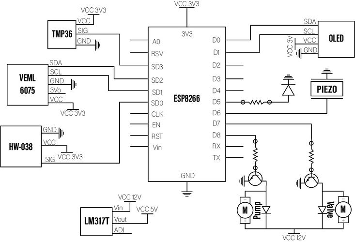
In addition to the flow chart we also created a block diagram over the electronic system. We included all the components that would fulfill the desired features. At this point we also considered the price and capabilities of our components.
The flow of the voltage and signals to the micro-computer were taken into account, when creating the diagram. The final version is shown below. However this only described how one unit would work.
Later on we will figure out how to make the product modular so more units can be connected and work simultaneously. This will be done with a master micro-computer that controls a number of slaves (one per machine).
By making the block diagram we learned that we had to check if all of our components could run on 5V (or something else). This would allow us to run the whole system on an ESP instead of an Arduino Uno - and luckily we found out that they all could as the ESP8266 can run on 3.3V.
Now we were ready to begin planing our prototypes.
PROTOTYPE PLANNERS
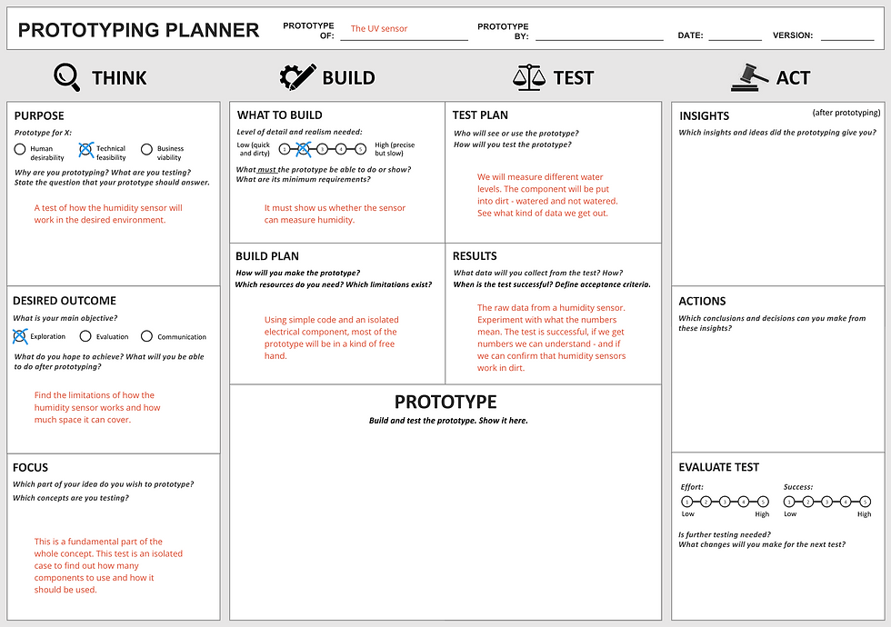
We started planning the prototypes needed to complete the first phase of the project. The point of the prototypes was to test the basic functions of the product. We planed to test: the UV-sensor, the temperature sensor, the water level sensor, and the pump. Furthermore we planed to do a CAD prototype and a prototype of the mechanical construction of the pump system. In this phase the main focus was to make one working unit. In the next phase (the 3 weeks period) we will work on connecting multiple units to make the product modular. You can see an example of one of our prototype plans below:


CONCEPT DRAWINGS
Zooming out from the technical perspective a bit, we drew up different concepts. The purpose of this was to specify the project further with shapes, sizes and connections as the main focus. We asked ourselves what would make sense for the water system and where the connecting electronics would be placed?
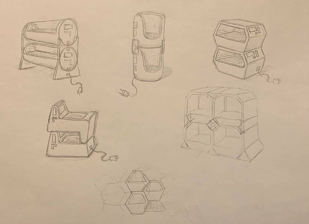
The drawings below show different versions of the same overall concept. The watering system and modularity were in this case our main focus.


.png)
To further explore possible designs and shapes we did some drawings of different styles. This gave us some exciting thoughts on what the essentials of the product could be. The product needed to have room for plants (top and roots), and for the water in which the roots of the plants would grow. It needed to be stackable and be able to connect sideways to allow one to connect more units to the first one. It also needed to have enough room for the LED light. Water transportation between the units had to be ensured as well. A water tank would also be necessary as well as a way to access the plants when they would be ready to harvest. You can see some of our concepts below:
DECISIONS AND CONCLUSION
We had changed our solution from a dirt-based one to a water-based one, as this was a smarter alternative.
To connect and deliver electricity, we had discussed making a magnetic surface connector for the transfer of voltage - but this would depend a lot on our final product shape .
We had decided that the product would have to be made modular, but we had not exactly decided how.
But at that time we just wanted to create a simple alpha prototype for the 13-week period part of the project. The modularity aspect would be looked at in the 3-week period.
PROTOTYPING
Executing our most important prototype tests and building the Alpha prototype
PIPE DISCUSSION, THE WATER FLOW MECHANISM AND FINALIZING THE DESIGN
What to do.. How to do.. the questions kept bobbling in our minds. We had to decide upon a final design. The most baffling, and stubborn element, was how the water should be transferred from unit to unit. As every other good goblin we sought the solution in others, to this we used the almighty tool of google, and a nifty researching tactic. I can confidently now say, I shouldn't be called blogger goblin, Pipe goblin would be a lot more fitting. I feel like my head went up and down pipes, as I was Mario trying to rescue Princess Peach out of Bowsers evil grasp. As a true goblin collective we discussed, and decided in plenary. We ended up deciding on a very simple system were the units only connects vertically. The units connect with barb-fittings.

Now we could decide on the final design. Our first design was the best suited for the new mechanism, so in that way we came full circle. CAD goblin went to work, intenssly working on the drawings, almost forgetting to eat. The rest of us went on a shopping trip to buy Strippers, and Hose(for wires and water). With this we were set for a great evening of fun of prototyping.

The prototyping went very well. We could confirm that the fittings worked as well as the pump. The most exciting thing was that we got to work with water!! Water always sends water goblin in a total ecstatic, elevating her mood to an unworldly level, which she happily and joyfully shared with the rest of us. A good mood is like Corona it contaminates faster than you can say "Fem flade flødeboller på en fladt flødebolle fad". Spirit was high, and there was love in the air. An incredible love for the process, our fellow goblins, and our fast growing Smart Farm.
WATER LEVEL SENSOR - PROTOTYPE
Continuing on our happy stride of water, we stayed in this happy element. We tested if we could measure the water level of a glas of water. We got it to read.. but it was extremely sensitive, just as the right wing politicians. We would have to thread carefully and take our precautions. The conductivity of the water had a great influence, and we would have to calibrate the water level sensor each time the water was changed. As a collective we would have to make another decision. We had to figure out how much information we needed from the water level sensor, ex. whether it needs to show 'low', 'medium', 'high' or if it was enough that the sensor measures whether there is water or not. This will be determined in the three week period.


TEMPERATURE SENSOR - PROTOTYPE
We dont wanna burn our plants, or dehydrate them by heating them up as if we were recreating global warming. A temperature sensor was in order. Written in arduino, and build on a breadboard the temperature sensor was now fully functioning, and we weren't going to allow our plants to suffer no more! We would now know when the environment in the box was too hot for the plants to strive. A success story, which deserved a cellebration. Hurray!

UV SENSOR - PROTOTYPE
The UV sensor worked to a certain extent and we were now able to read data from the sensor. However, the sensor was not as sensitive as we'd wished for. It never asked how I was doing, only work work work. A goblin needs more, a goblin needs sensitive attention. We wanted to find the exact measurements for the most optimal wavelength plants grow under, so we know if the Sun gives the right illumination for optimal growth. We need to further develop a scope under which optimal growth is. We will measure the right range for this growth under next test.

CAD - PROTOTYPE
The CAD model gave us the inside perspective of how everything will look in practice, and as we all now a picture says more than a thousand words. Even though we are rather talkative, we often talk over each other, and therefor a common picture, displaying mechanism and functions are crucial. If we didn't have this tool, I'm sure it would be a complete goblin mayhem. Issues can vary in size and this means that a lot of micro-adjustments were done to the overall design. Sensor placements and other features also had to be slightly adjusted for unnoticed issues. When working with CAD in general, a lot of experience is earned with the method of 'trial and error' which makes the development phase very tedious. We developed the parts aside from each other, then collected them all at last like Frankenstein, giving them new life and meaning when put together. The individual parts could be redone and adjusted multiple times with ease, this was done to get the best solution in the smartest and most optimal way.

ALPHA PROTOTYPE 1.0
For the Alpha prototype the Goblins chose to focus on getting the power source, pumping system, water level sensor and IoT element working. This was critical functions for the life and well being of the plants. Without sustenance the hero won't work! As the system is quite complex with different features, we decided to only create the critical water system.
With the diagram as a recipe, and Anna's place as our kitchen we went to work, as the chefs on a high tier restaurant. The goblins got down to business. First the system was created on breadboard, with an LED to just check if the transistor system worked. With a success story we went to the soldering station. With the fumes filling the air, as on the battlefield we soldered.
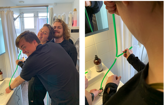
After having fried most of our brain cells - soldering in our bathroom using a hair dryer as ventilation - we finally got the soldering on our vero board right. On the board was our esp, 12 V power supply, transistor, diode, pump and water level sensor.
The pump was controled on Nodered, sending signals on the magical waves of the internet.. With part 1 working we began on the sequel. The magnificant sequal would introduce a new star the water level sensor. The new cooperative would include complete synergy, having the water level sensor control if the pump should run. As they in the system would be on different ESP's we would have to puplish information from the water level sensor, and getting it on the other. Though there was distractions the goblins overcame, and conquered. This is the blogger goblin signing out.. so long, keep low, and keep teasing. That is the goblin way :))


The pump is working!!

Controlling the water level sensor via NodeRED

USE CASE

CAD PROTOTYPE 2.0
Fittings for both water electricity and connectivity is being thought out in this blogpost. A lot of different ideas and thoughts will be discussed here.
Electricity
A lot of different requirements are needed here. First the electric connections need to either be wirelessly or manually connected through the different grow boxes, specifically power from the mother box through the pipe grid to the slave boxes. Getting a system that seamlessly connects electrical lines through the pipe grid isn’t easy, moreover the mother box is placed at the bottom and needs to somehow transfer power and receive/transmit data to the slave boxes. This could be done through direct connectivity from cables, but this might be hazardous with the running water throughout the system. It is hard to find a smart way of seamlessly creating a connection between the electrical lines without it being complicated for the user. Another idea could be to use wireless transfer of electricity like the coil used in phones. This would allow us to seamlessly conduct electricity from box to box without any physical cables running from box to box and needing to be manually connected by the user. This way the only wiring needed is the wiring for the sensors in every individual box. The slave boxes will then have a conduction coil in both the top and bottom. One problem with this is that there is no direct line of communication with the mother box and slave boxes. This might be solvable if the communication between the mother box and the slave boxes was wireless or somehow transmitted through the conduction. If we go with this idea we would need an MPU in each 'slave' box.
Water
The water systems could be done either through the back of the box or inside the pipe grid. The main issue with the water system through the pipe grid would be how complicated it is to build for the manufacturer and for the user to use. If any pipe should break, then it would be hard and complicated to take it apart and fix it. Doing the water system in the pipes would be the most elegant way of doing it, but this would require a lot of thinking on how to connect it between the mother box and slave boxes. Currently, all pipes are connected with barb fittings (the same used in chemistry classes). These have a lot of flexibility and modularity which makes them easy to use. Connecting the pipes between the boxes could either be done with a cap that can either be a stopping point or a connection point. Getting the pipes to turn is the hard part since this would mean that a T-shapes system would have to be created in the ball connection on one of the corners of the box, so the water can still pass through without any problems.
A second way of doing it, would be doing it all in the back of the box. Here a water outlet would be placed on the back of the mother box and a connection line could then manually be placed by the user. This gives the user the freedom of piping the system themselves in any way they want, this would also make it easier for the user to maintain and fix if any problems, should they occur. Valves would in this case keep the water from getting into the boxes if a different water supply was used than the pumps from the mother box, like as a direct water connection. The slave boxes would then have a T-shaped system where the water would be redirected into the valves and up towards the next slave box. A small cap would then be placed on top if no other slave box was put on. The main issue with this solution is that it takes a lot of space that could have been spared by doing the water piping through the pipe grid.
SYSML DIAGRAMS


In the SysML section we created three diagrams which shows the function flow for each diagram. In the diagrams it shows the main function that the prototype will need the operate. The SysML is a helping tool that will help us have an overview over the system's required code and what the loops need to have to control the system between the IoT and the electronics.
The first diagram shows the automatic control of water, light and temperature of our system and in which order they are checked. First the system checks if the water level in the slave tank is too low and then proceeds to send a signal to the Master MPU to fill the 'slave' tank. The information is sent both to the app and the OLED screen. The system then proceeds to check the light and adjusts it if needed. Lastly it checks the temperature and alerts the user if the temperature is too low/high.
The second diagram shows how the user is able to manually control the water and light settings if they wish.
The third and final diagram illustrates how the user sets up additional 'slave' boxes and links them to the master.
ALPHA PROTOTYPE 2.0
After getting feedback on our initial ALPA prototype the Goblins realized that we had to get the water level sensor from a 'slave' MPU to speak to the Master MPU and signal the pump to fill the 'slave' tank to fulfill the standards of our key system prototype.
We realized that using the vero board was complicating things for us, and decided to simplify the prototype in order to actually get it working. The setup that we were testing was the Master MPU with an external power source and an additional 'slave' MPU with the water level sensor and temperature sensor. The goal was to get the slave MPU to send messages to the Master MPU to control the pump, when the water level sensor registered a low water level.

We used a transistor to be able to control the power going to the pump via the MPU. To make sure that the flow of the current was one-directional we use a diode in the setup with pump.
The goal was now to connect it all via IoT and be able to have the water level in the tank control the pump. Before actually connecting the pump, we tested the system with an LED. Initially we had problems controlling the power source via the transistor, but we got the subsystem to work in the first place. As the pump needed more voltage, we had to do some alternative wiring. This caused us a lot of trouble, as the components didn't fit the right specifications.
We found a list of problems that we sought to fix, but didn't succeed. We first tried to finish the system holding a transistor:
-
There was a passive amount of voltage coming out of the MPU, that we couldn't stop - even though the different digital outputs were set to "LOW" (off).
-
The transistors required a very specific amount of power (amperes), that after several attemps seemed impossible to fit the description of.
-
The power of the power-source was only providing 9V, but the pump requires 12V to run optimally. We have had the pump running before, but in the system, there's too much of a loss.
We tried another wiring/solution. This solution makes use of a "relay" (SRD-05VDC-SL-C). This relay was going to make it possible for us to provide enough power and simultaneously control whether power is allowed to flow through. We ran into the following problems:
-
Signal seemed unreliable, and we couldn't figure out where the connection/signal went wrong. Multiple wires exchanged for no use.
-
There was not any power flowing through the relay (most of the time), as we couldn't even light an LED.
We got every other subsystem to work, and got different components to work from the same combined code.
We also got a (partly) working subsystem working: the OLED, the water level measurer, the Wi-Fi connection (and NodeRED), and at last the connection/signaling to the pump.
Going forward, the immediate focus is to make a system/wiring that allows us to (1) power the pump, and (2) control the activation of it.
Lastly, we figured out that one of the main problems with our system is the fact that the MPU we use only has ONE analog pin. In our system, we ideally need at least three analog pins for water level, UV sensor, and temperature. We therefore decide to focus only on the water level sensor at the moment and then figure out how to connect the whole system in the three week period. This will likely result in either an Arduino with a WiFi-module, or an excessive use of ESP8266 (MPU's) wireless connections and sensors.
CONCLUSION TO ALPHA PROTOTYPE
We can get the system to work to the extent that we can control the power source to the pump
via commands to NodeRED. However, since we had problems with the transistor and diode, we showed this principle by using an LED, validating the feasibility of our system. Furthermore, we managed to get the water level sensor to publish to the OLED screen. Lastly, we managed to publish the water level to the app on a "gauge chart" via NodeRED and also controlling the LED (stand-in pump).
GALLERY
Enjoy renderings and other images of our product and development


